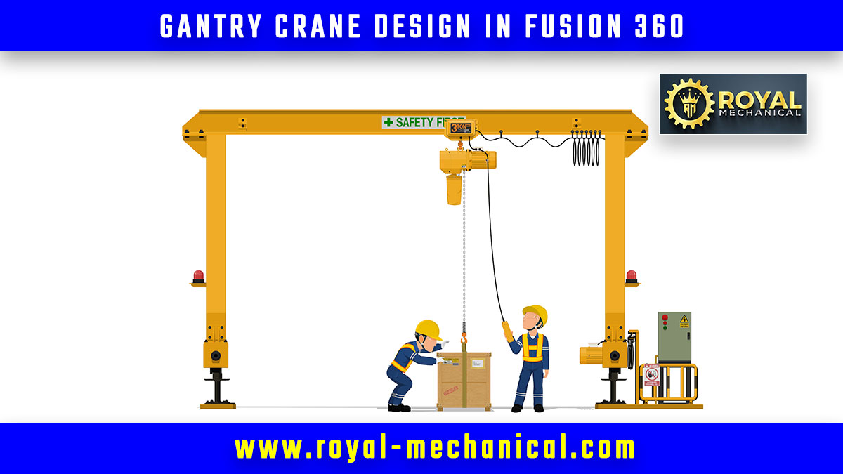
Designing complex structures like gantry cranes in mechanical engineering demands a comprehensive understanding of engineering principles and cutting-edge tools. This guide delves into the intricacies of creating a Gantry Crane using Fusion 360, a powerful software tool that empowers mechanical engineers to turn their visions into reality. Let’s embark on a journey to uncover the secrets of gantry crane design, all while harnessing the potential of mechanical engineering prowess.
Understanding Gantry Cranes in Mechanical Engineering
Gantry or portal cranes are pivotal in the manufacturing and logistics industries. These structures provide the ability to lift heavy loads with precision and efficiency. As a mechanical engineer, mastering the art of gantry crane design is an achievement that enhances your problem-solving skills and showcases your engineering prowess.
Fusion 360: The Mechanical Engineer’s Swiss Army Knife
Fusion 360, Autodesk’s multidisciplinary design software, has become a staple tool for mechanical engineers. Its seamless integration of CAD, CAM, and CAE capabilities makes it an indispensable asset in engineering. With its user-friendly interface and comprehensive features, Fusion 360 empowers engineers to design, simulate, and visualize their creations.
Step-by-Step Guide to Gantry Crane Design
1. Conceptualization and Requirements Analysis
Every successful project begins with a solid plan. Define the requirements of your gantry crane, considering factors like load capacity, span length, and operational environment. Fusion 360 lets you sketch your ideas, enabling you to visualize the crane’s structure before diving into the detailed design.
2. Structural Design and Simulation
Utilize Fusion 360’s robust design tools to create the skeletal framework of your gantry crane. Implement trusses, beams, and supports while considering load distribution and stress points. Fusion 360’s simulation capabilities enable you to test your design virtually, identifying potential weaknesses and optimizing the structure for maximum efficiency.
3. Mechanical Components Integration
Integrate the mechanical components that drive the crane’s functionality, such as trolleys, hoists, and motors. Fusion 360’s parametric modeling allows you to adjust dimensions and parameters seamlessly, ensuring that every component fits perfectly within the overall design.
4. Material Selection and Analysis
Mechanical engineering thrives on material science. Select materials for each component of your gantry crane, considering factors like strength, weight, and durability. Fusion 360’s material analysis tools assist in making informed decisions, ensuring the crane’s reliability under various conditions.
5. Visualization and Presentation
Presenting your design effectively is crucial. Fusion 360 enables you to create photorealistic renderings and animations that showcase your gantry crane’s capabilities. Whether for client presentations or internal reviews, Fusion 360’s visualization tools enhance your communication as a mechanical engineer.
Conclusion
The fusion of mechanical engineering expertise and Fusion 360’s capabilities creates remarkable structures like gantry cranes. This guide has illuminated the process of designing a gantry crane using Fusion 360 while embracing the essence of mechanical engineering. As you continue your journey in the field of mechanical engineering, remember that every design you create has the potential to reshape industries and drive innovation forward. So, equip yourself with knowledge, harness the power of tools, and let your engineering aspirations soar to new heights.


